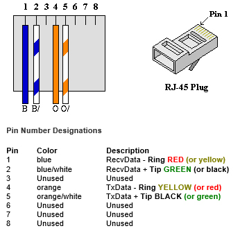
Surface Mount Rj45 Jack Wiring Diagram
31+ Surface Mount Rj45 Jack Wiring Diagram Images. The wall jack may be wired in a different sequence because the wires may be crossed inside the jack. The colors i see on this jack go:

There is no electrical difference between the t568a and t568b wire sequences, so neither is t568b is the standard followed by the majority of ethernet installations in the united states for rj45 color code.
Rj45 pin # (end 1). When i add a rj45 jack connector to my pcb board, there are (depending on how the connector is build, of course (with led or not, etc)) normally 8 pins for the 8 wires in the cat5/6 cable. Pinout diagrams and wire colours for cat 5e, cat 6 and cat 7. Which rj45 serial pinout does my opengear device support?
0 Response to "Surface Mount Rj45 Jack Wiring Diagram"
Post a Comment